Thursday, May 4, 2023

Stabilator trim motor assembly

 Decided to go ahead and assemble the stabilator trim motor assembly since I have the parts all ready to go. - 1.75 man hours.

Started by riveting on the reinforcement tabs to the pivot ears of the bracket that holds the trim servo.

Must use the angle tool to get these rivets.  The manufactured head needs to go on the inside.

Match reaming the parts together and to full size of 1/4"

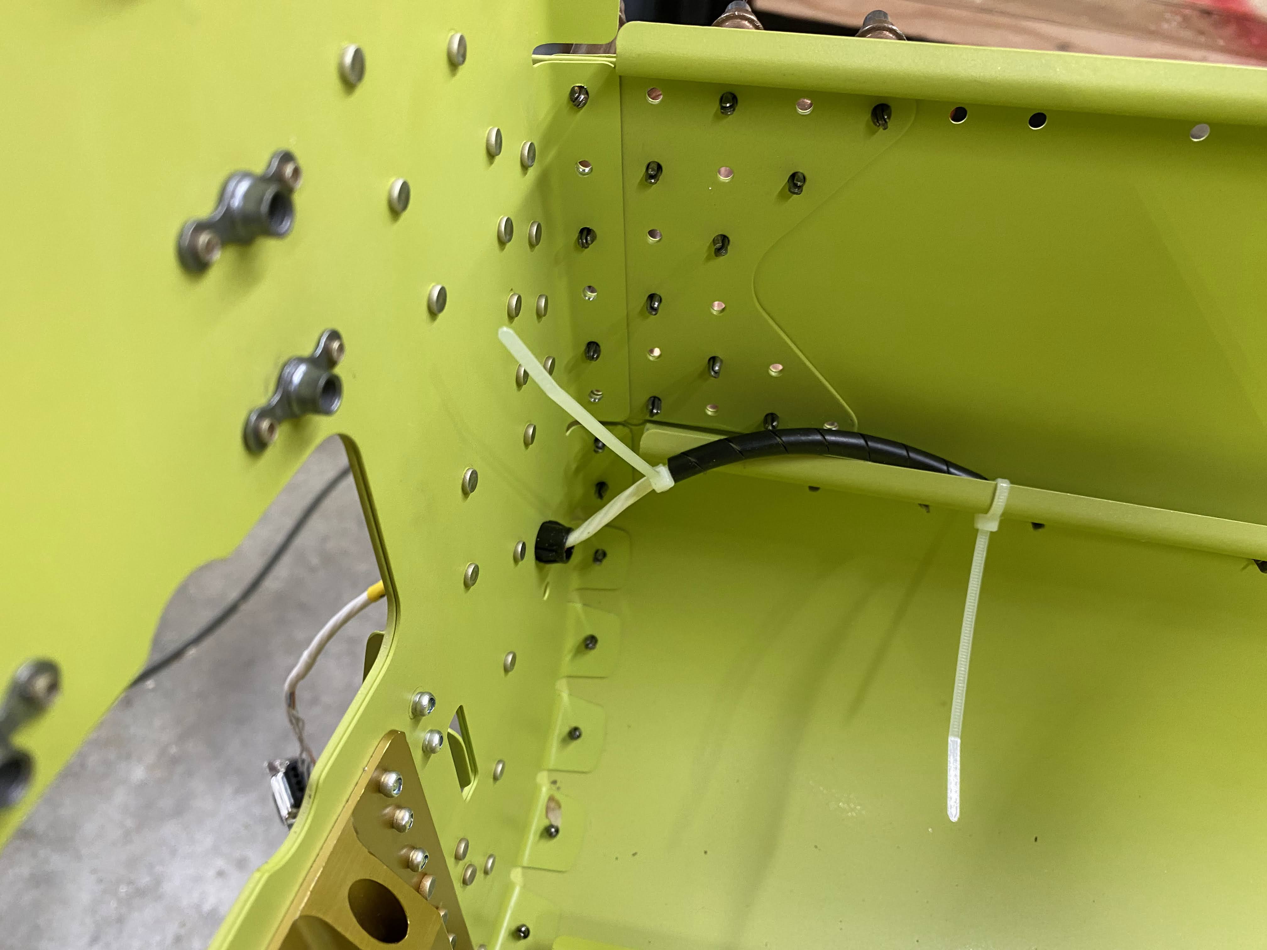
Installed the snap bushing.   Weird how Van's puts this hole so close to the edge that it leaves a notch in the part.

Installed the bushing in the linkage arm.  Used the vice and a socket trick.

Installed the bushing in the servo mount tray.  Used the vice and a socket trick.

I did not get any pics of the process of filing these bushings to the correct width.  Van's used to be known for stating "You are building an airplane, not a Swiss watch!".  That has obviously changed because there are some critical dimensions that are emphasized in several places on this build so far.  

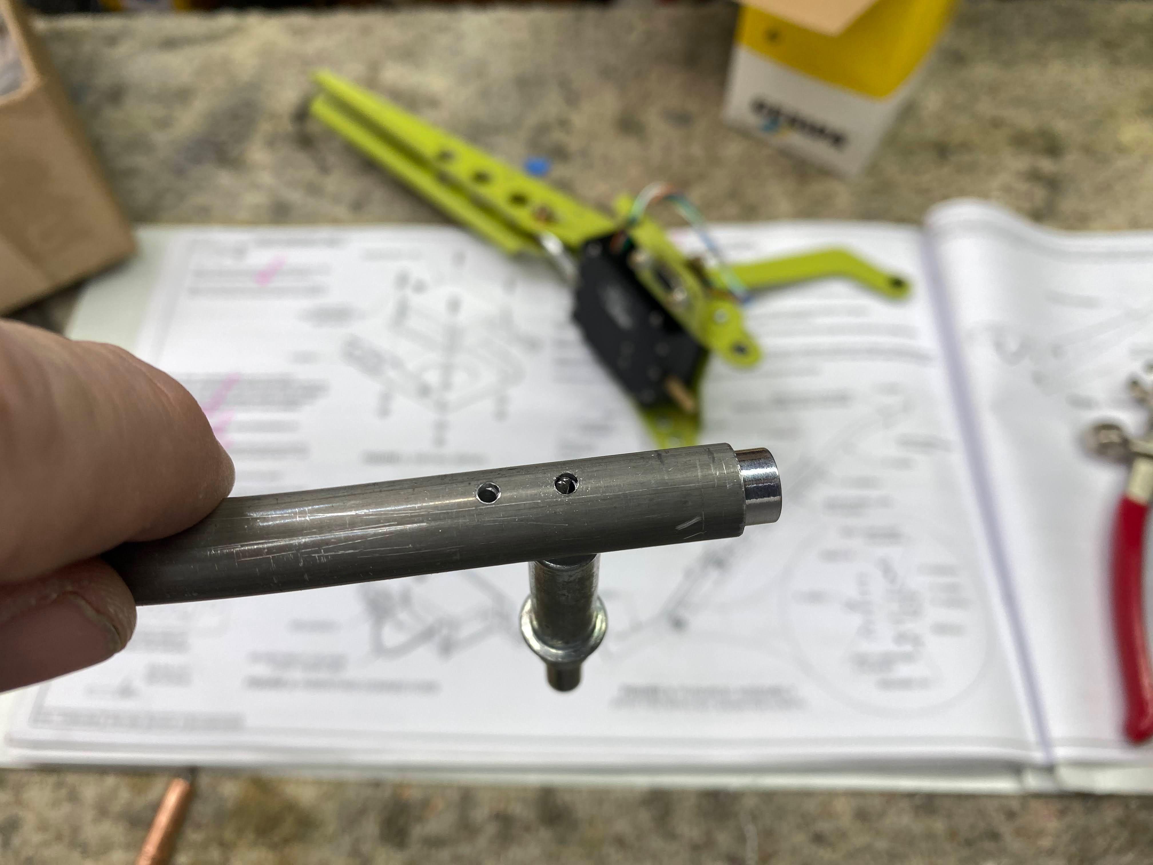
Did not have to cut my shaft.  It was exactly as required by the manual.

Getting this clocked correctly was a pain in the rear!  The bushing has to be shortened to get the clevis perpendicular to the server housing.  Twice I went too far and had to remove more material.  Finally nailed it.  You will need some Red Lock-Tite to assemble this!

Fastened the trim servo to the tray with the hardware specified with the exception that the plans call out a non stainless screw but all that are provided in the hardware kit are stainless.

Stripped and crimped the pins on the servo power and potentiometer leads.  Inserted them into the 9 pin D-shell connector.  Temporarily installed the hardware that will eventually hold the connector together and to the tray.

Installed the hardware for the servo shaft clevis.  Did not fold over the cotter pin yet.

And the lever arm hardware.

Had to match drill the clevis plates to the pushrod.

All drilled and deburred.

Match drilled the threaded insert to the pushrod.  Used a rivet mandrel to align the parts.


This is the second time Van's has you squeeze 3/32 universal head rivets.  Problem is they do not list a 3/32 universal head rivet set on the required tools list.  Luckily I have one in my arsenal.  

Done....

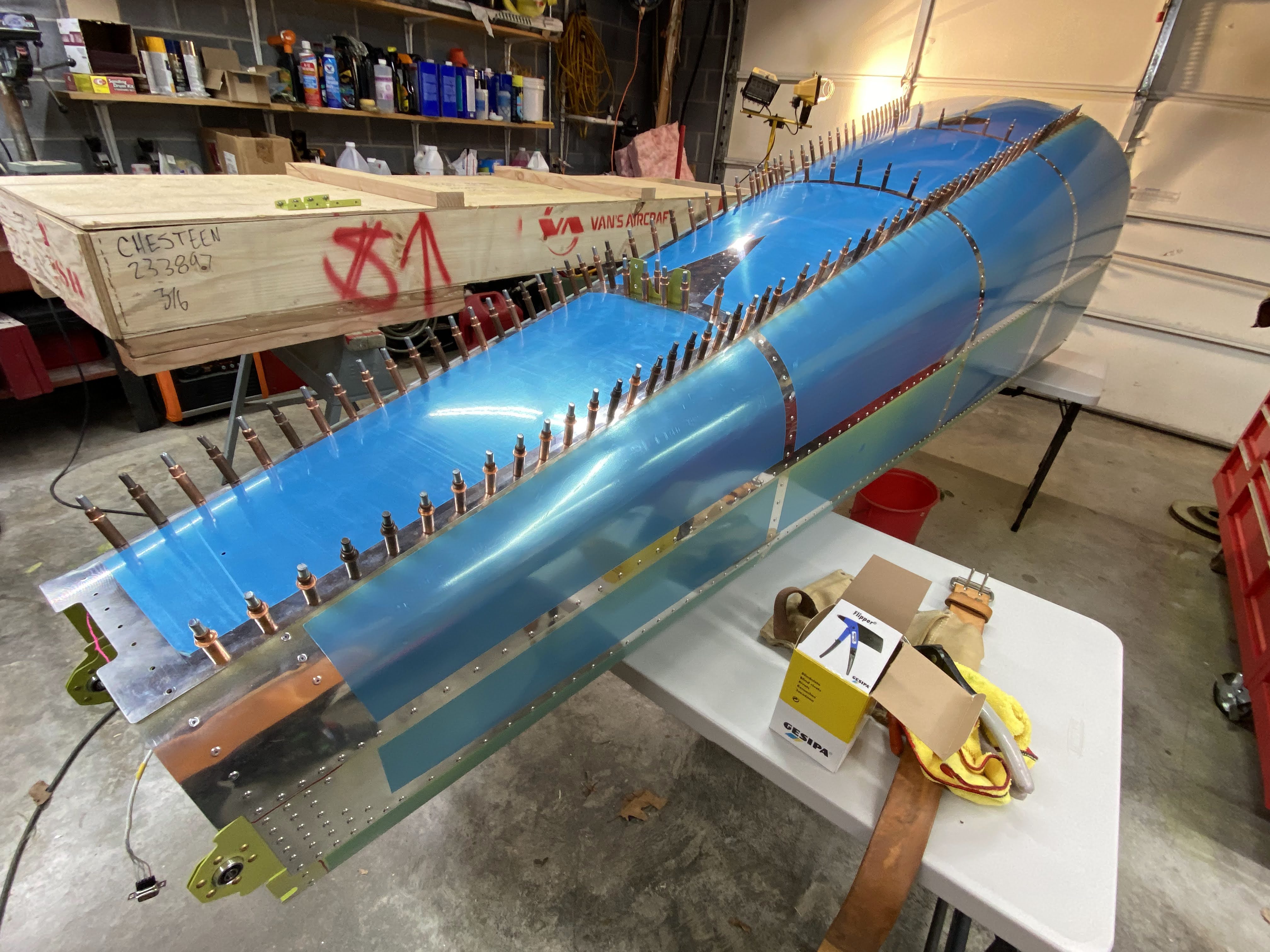
The clevis plates get riveted to the pushrod using these sealed blind rivets that are normally used to put fuel tanks together.  I imagine the small clearance inside the tube is why these were selected.  The opposite side actually interferes with the setting of the rivet so you have to push in toward the pushrod as you pull the rivet.
Done!

Temp installed the bearing and jam nut.

Here is the assembly as it will be installed later during final assembly.  I used a battery to test its operation but forgot to take a video.


Wednesday, May 3, 2023

Tailcone assembly part 3

 Finished up the tailcone assembly!  - 5 man hours.

Started today by finishing up the rivets on the right side.


Right side done!

Preparing the forward vertical stabilizer skin attach rib.  Final drilling the holes to size.

Dimpling the screw holes.

Dimpling the rivets.

Riveting on the nutplates.

Top skin cleco'ed on

I am not 100% happy with how the top skin overlap came out on the aft end.  There are a couple puckers that left a very slight gap which should get hidden by paint but it bothers me.  Also between the aft rivets is not as smooth as the rest of the skins.  A little wavy.  I followed the directions on breaking of the skins and increasing the break on the aft end but not sure if I went too far or not enough.  It is definitely acceptable but not what I would have liked.


Riveted the vertical stabilizer front skin attach rib to the tailcone.


Top skin rivets done!

Riveted in the center J stiffener and the magnetometer mount brackets.


Tailcone all done!


Tuesday, May 2, 2023

Tailcone assembly part 2

 Continuing to work on the assembly of the tailcone. - 3.5 man hours

String goes in to help pull in the stabilator control cables.

Wiring harness goes in for the stabilator trim servo.  It gets pulled in up to the red heat shrink.

I have seen where some kink this cable to go all the way to the end of the J stiffener.  I ain't doing it!  I also added a piece of spiral wrap where the cable crosses the edge of the stiffener.

Coiled up for future use.

Installed the static system ports which are just blind rivets.  Van's figured out the secret sauce to static position error many moons ago.  Many people have tried to improve on the design only to find that these rivets make the best static ports.

After the rivet is set, you have to remove the mandrel.  I drilled a hole in a piece of hardwood that would go over the rivet tail and leave room for the mandrel to pop out.

Pressed up against the skin, it keeps you from damaging the skin.

I cut a short piece of the mandrel off to use as a punch.  Hit it with a hammer and the trapped mandrel comes right out.

Tubing gets installed over the rivet tails and then secured to the bulkhead.

The zip ties get tightened on the right side but not the left to allow for more stuff later.

Mandrel is gone!

Detail of tubing slipped over rivet tail.

I used this to seal the tube to the skin.

A dab will do you.

Seems cavemanish but it works.


A "T" is installed in the middle of the lines.

Have to heat the larger diameter line to slip over the T fitting.


Next I finished up the rudder cable bushing brackets.

They get drilled to the skins.

Then riveted.

And a bushing installed.

Then another string is placed that will make it easier to pull in the rudder cables later.

Left side rivets done.


A ton of rivets here!

A shot from the front to the back.

My second box is empty.  2000 pulled rivets so far!